Description
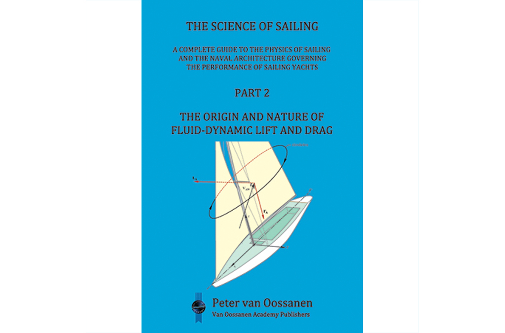
“The Origin and Nature of Fluid-Dynamic Lift and Drag”
Equations were derived in Part 1 which revealed that the speed of sailing craft is primarily governed by the values of the aerodynamic- and hydrodynamic lift- and drag forces. It is thus important that those involved in the design of wind-powered boats, yachts, and ships, have a thorough understanding of the origin and nature of fluid-dynamic lift and drag and, furthermore, possess knowledge on how to obtain high levels of lift and low levels of drag.
Part 2, comprising Chapters 5 and 6, explain the origin and nature of fluid-dynamic lift (Chapter 5) and drag (Chapter 6).
Chapter 5
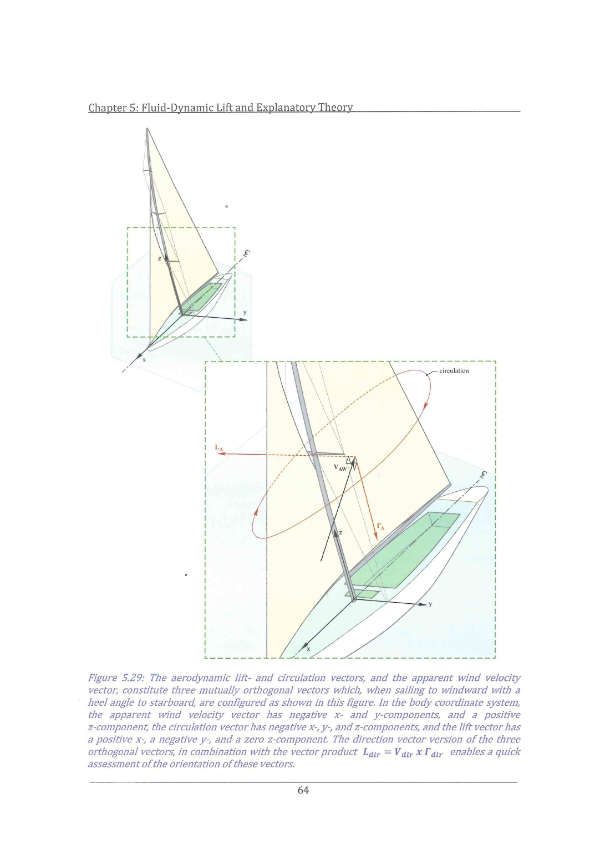
Chapter 5 commences with a description of the origin and nature of fluid-dynamic lift and describes how lift on a body is developed. This is followed by a derivation of the Bernoulli equation linking velocity and pressure along a streamline in the flow, and a description of some properties of the pressure distribution on a body, the integration of which results in the magnitude of the fluid-dynamic lift force and the pressure drag. The concept of an ideal fluid is then introduced, followed by a concise description of classical potential flow theory, the theory by which the development of a lift force on a body with circulation around it can be explained and calculated. This section is divided into a number of sub-sections so as to be able to present such concepts as velocity potential, gradient operator, impulse pressure, the continuity equation, divergence, Laplacian, stream function, circulation, vorticity, sources and sinks, and doublets, in a systematic way. Potential flow is then used to calculate the flow around a source, a source and a sink together, and around a doublet, in uniform parallel flow. The resulting flows are representative of those around various bodies. The flow around a rotating cylinder is then derived by adding circulation to the flow around a doublet. The resulting flow is capable of developing lift, in a direction perpendicular to that of the incoming, free-stream velocity. Although this flow model, and the associated mathematics, is relatively simple it is nevertheless able to predict a meaningful level of the lift force. The integration of the pressure distribution around this cylinder results in the magnitude of the lift force, thereby deriving the so-called Kutta-Joukowski theorem that expresses the relationship between lift and circulation. A method for establishing the direction of the lift vector for the three-dimensional case when (sometimes) this direction is not so obvious – as in the case of sailing craft – is also described. Finally, the on-going discussion between aerodynamicists concerning the correct and incorrect explanation for the origin of lift is commented on.
Chapter 6
Chapter 6 deals with the basic aspects of fluid-dynamic drag and its components. Much of the subject matter presented is of a general nature, applicable to all boats, yachts, and ships, except for the section on the additional drag incurred when the hull adopts heel and leeway, which is obviously pertinent for sailing vessels only. The focus in this chapter is more specifically on ship-type bodies operating in the vicinity of the air-water interface than in the case of Chapter 5 dealing with fluid-dynamic lift. This is due to the fact that in the vicinity of the air-water interface bodies possess components of drag that do not appear when wholly operating in air or when deeply submerged. The researchers primarily responsible for the further development of our understanding of fluid-dynamic lift were, with few exceptions, aerodynamicists. This is not so in the case of fluid-dynamic drag. The subject still referred to as “resistance” by most workers in the field has been primarily developed by ship-oriented hydrodynamicists and naval architects. This is because the performance of ships is particularly governed by the forces opposing forward motion (more so than in the case of aircraft), and the key to solving ship-oriented performance issues requires in-depth knowledge concerning the optimum shape of hulls and hull appendages in relation to their drag characteristics. Fluid-dynamic drag is therefore treated from the perspective of the hydrodynamicist and the naval architect, although many of the topics to be considered are also of importance for the drag of sails, masts, and rigging.
The chapter commences with a description of the origin and nature of fluid-dynamic drag by defining the two causal components of drag that can, today, be directly calculated with advanced Computational Fluid Dynamics (CFD) codes. The classical division of drag into a frictional- and a residual component, as adopted by William Froude, is then described followed by a section revealing that such a division is based on a component primarily dependent on Reynolds number, and a component primarily dependent on Froude number. The Telfer diagram is then introduced to show how the total drag of a body operating at or near the air-water interface can be divided into components based on their physical nature. On comparing the component of drag dependent on Reynolds number with the friction drag of the equivalent flat plate, the effect of the three-dimensional shape of the hull on viscous drag can be determined. This results in the concept of a “form factor”. The equivalent flat plate is the plate with the same wetted area and the same length as that of the subject body. This form factor has two components, the first of which is the difference between the friction drag of the hull or body with the drag of the equivalent flat plate, and the second of which is the viscous pressure drag.
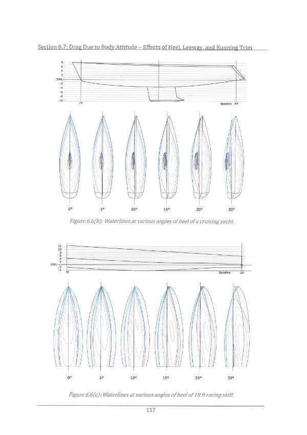
A major part of Chapter 6 is devoted to a description of the additional drag incurred when the hull adopts a non-zero combination of heel, leeway, and running trim. This is of particular significance for sailing craft, which heel and adopt some degree of leeway on every course relative to the direction of the wind. This additional drag is referred to as the drag due to body attitude. One of the main components of the drag due to body attitude is associated with the lift that is generated by the hull, keel, and rudder, as soon as these adopt a non-zero angle of attack relative to the incoming flow. This component of drag is referred to as lift-induced drag. The origin and nature of this component is presented in some detail.
A particular fundamental division of drag into components is obtained when applying Newton’s second law to the case of the force imparted by the hull on the flow around it. This force is equal to the consequential rate of change of momentum of that flow. By virtue of Newton’s third law, this force is equal and opposite to the resultant hydrodynamic force the hull needs to overcome in maintaining a constant velocity. This approach is mathematically pursued, resulting in a division into viscous drag, wave pattern drag, and lift-induced drag. Finally, a chart is presented dividing total drag, as found in the case of a vessel sailing in waves, into its various components by way of their dependence on Reynolds- and Froude number, and according to whether they are shear- or pressure based.
Attention! If you wish to order from outside the Netherlands OR more than one book please use this form.